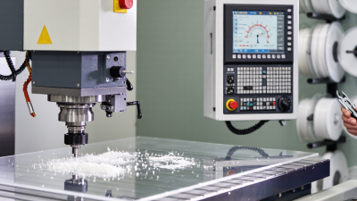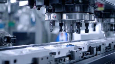
Injection molding tooling is more than a steel form that gives plastic its shape. It controls how material enters, cools, and leaves the mold. A cavity that is slightly out of tolerance can affect fit across thousands of parts. Cooling channels, vents, and gates also shape cycle time and surface quality. Small details matter.
Injection molding consultant John Bozzelli captures the principle with a familiar industry saying: “The mold is the heart of the process.” Tooling deserves that attention because design decisions become physical in every shot. A poorly placed gate may leave a visible mark; uneven cooling can cause warping near a thin wall. These are not abstract risks. They can show up as scrap, delays, or difficult assembly.
For product teams, investing in suitable injection molding tooling can support repeatable production and reduce costly adjustments later. The right choice depends on part geometry, material, expected volume, and maintenance needs. A high-cavitation tool may suit a large production run, while a simpler design may be more practical for lower demand. There is no universal answer. Even careful planning can miss something; real parts sometimes reveal problems that drawings do not. That is worth admitting. A clear tooling plan, paired with experienced review and sampling, helps teams catch those issues before full production begins.
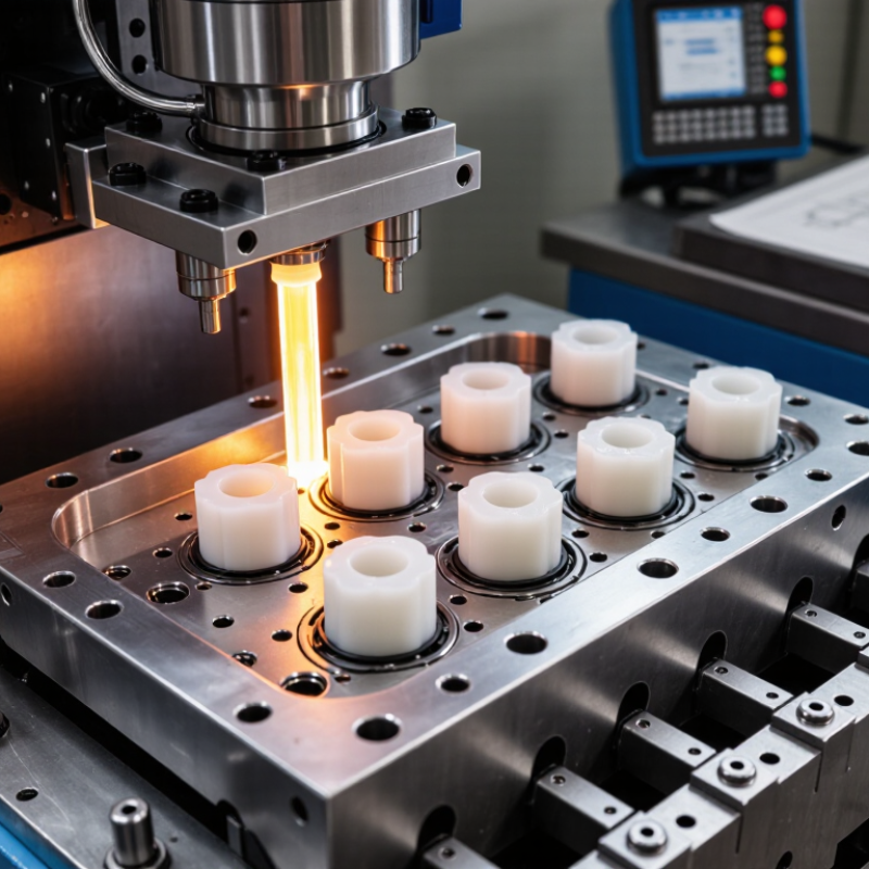
Injection molding tooling is more than a steel block. It is the complete mold assembly that shapes, cools, and releases each part. Its core components include the mold base, cavity, and core, which form the part’s outer and inner surfaces. The runner and gate guide molten resin into the cavity. Cooling channels remove heat, while vents let trapped air escape. Ejector pins or sleeves push the finished part out. Small details matter. A poorly placed gate can leave visible marks; uneven cooling can cause warping.
Tooling may also include slides, lifters, replaceable inserts, and alignment features for parts with undercuts or changing dimensions. These choices depend on the resin, part geometry, expected production volume, and maintenance plan. Grand View Research estimated the global injection molding market at USD 284.7 billion in 2023, underscoring the scale of production that tooling supports. The figure describes the broader market, not tooling costs. In practice, a polished tool is not automatically a good one. Cooling access, vent placement, and ease of repair can matter more than appearance. Designers sometimes accept compromises, but documenting them helps prevent costly surprises during production.
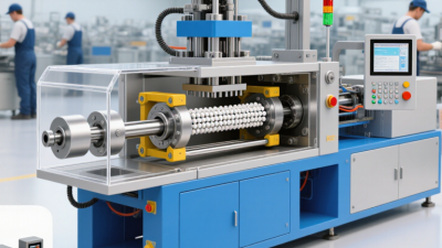
Why Is Injection Molding Tooling Important?
How Tooling Shapes the Molding Process
The mold is more than a container for molten plastic; it controls flow, cooling, and part release. Its cavity defines the part’s shape, while the gate directs material into that space. Gate position and size can affect weld lines, pressure, and visible surface marks. Small choices matter.
Cooling channels help remove heat evenly, but their layout must account for the part’s thickness and geometry. Uneven cooling can contribute to warping or longer cycle times. Vents also need careful placement: trapped air may cause burns or incomplete filling. These details are easy to overlook on a drawing.
During production, engineers may adjust temperature, injection speed, or pressure to address defects. Yet process settings cannot always compensate for a poorly designed tool. A deep, narrow feature, for example, may be difficult to fill and cool consistently. Tooling decisions should reflect the resin, part shape, expected volume, and finish requirements. Even then, early estimates can miss real production behavior. Trial runs reveal surprises, and sometimes the tool needs revision. That is not wasted effort; it is useful feedback.
Typical mold shrinkage varies by plastic, so tooling must account for material choice when sizing the cavity.
Bars show the midpoint of each typical shrinkage range. Actual shrinkage depends on the material grade, part geometry, and molding conditions. Toolmakers use material-specific shrinkage estimates to size cavities; cooling layout and other tooling features also affect part dimensions and consistency.
Injection molding tooling shapes more than a part’s outline. Cavity dimensions, gate position, venting, and cooling-channel layout influence how resin fills and solidifies. A slight mismatch at a shutoff can leave flash; uneven cooling can pull a flat panel into a visible bow. Small errors travel. Once production begins, tool wear or temperature differences may also shift dimensions between cavities and batches.
ISO 20457:2018 sets tolerance frameworks for plastic moulded parts, emphasizing that tolerances should reflect material, geometry, and manufacturing conditions. AIAG’s Statistical Process Control reference describes capability measures used to assess whether a process can hold specified dimensions; Cpk 1.33 is a commonly applied production target, not a universal guarantee. A stable tool helps a process reach such targets, but measurement data must confirm it. I would not assume a polished cavity alone ensures consistency. Resin changes, machine settings, and maintenance matter too.
Tips: Check critical dimensions from every cavity, not just one sample. Record cavity temperature and part weight during trials. If dimensions drift, inspect vents, cooling balance, and wear before changing machine settings. Then inspect.
Why Is Injection Molding Tooling Important?
How Tooling Influences Production Speed and Cost
A mold is more than a cavity that gives plastic its shape. Its cooling channels, vents, and gate locations affect how quickly each part can be made. When heat leaves the part evenly, cycles can be shorter and warping less likely. Poorly balanced cooling may create uneven parts, extra inspections, or scrapped pieces. These delays add cost. Tooling also influences how often production must stop for cleaning or repairs.
Tips: Ask how the mold will be cooled, maintained, and checked for wear. Review likely cycle times with a sample part, not just an estimate. Small design changes can matter.
A durable mold may cost more upfront, yet reduce repair downtime across a long production run. For a short run, elaborate tooling may not pay for itself. The right choice depends on part complexity, expected volume, material, and quality targets. Estimates can still be wrong; real production often reveals details that drawings miss. A careful trial run helps identify slow cooling, sticking, or flash before full production begins. Tooling decisions deserve that attention.
| Tooling dimension | How it affects production speed | How it affects cost | Practical consideration |
|---|---|---|---|
| Cavity count | Multiple cavities can produce several parts in one machine cycle, increasing output per cycle when the cavities fill and cool consistently. | More cavities usually increase mold complexity and initial tooling cost, while potentially lowering tooling cost per part at higher volumes. | Match cavity count to expected demand, machine capacity, and the ability to balance filling across cavities. |
| Cooling layout | Well-positioned cooling channels help remove heat evenly. Cooling time is often a significant part of the molding cycle. | More involved cooling designs can raise tooling cost, but shorter, more consistent cycles can reduce machine time per part. | Design cooling around the part’s wall thickness and geometry; uneven cooling can contribute to warpage and longer cycles. |
| Tool material and hardening | A durable tool can support sustained production with fewer interruptions for repair or replacement. | Tool steels and hardening processes can increase upfront cost; the appropriate choice depends on expected production volume, resin, and wear conditions. | Consider abrasive or corrosive materials and the required tool life when specifying mold materials. |
| Gates and runners | Gate location and runner design affect how quickly and evenly molten plastic fills the cavities and how reliably parts can be ejected. | Runner layout affects material use and scrap. Hot-runner systems can reduce runner waste but add tooling complexity and maintenance requirements. | Choose the system based on part geometry, resin, quality requirements, and production volume. |
| Venting and ejection | Adequate venting lets air escape during filling, while a suitable ejection system helps release parts consistently and reduces cycle interruptions. | Poor venting or ejection can lead to defects, rework, scrap, and unplanned maintenance, increasing the cost of acceptable parts. | Plan vent locations and ejector placement with part geometry and surface-quality requirements in mind. |
| Replaceable inserts | Replaceable wear or detail inserts can allow localized repairs without rebuilding the entire mold, helping limit downtime. | They may add design and machining work initially, but can make some future repairs or product-detail changes less costly. | Consider inserts for areas likely to wear, require frequent changes, or need close dimensional control. |
| Maintenance access | Accessible components can make routine cleaning, inspection, and servicing more straightforward, reducing avoidable production delays. | Serviceable tooling can help control maintenance labor and downtime costs over the mold’s operating life. | Include maintenance access and a planned inspection schedule in the tooling design and production plan. |
| Part geometry and draft | Geometry that releases cleanly from the mold can support reliable ejection and reduce cycle disruptions. | Complex features, tight tolerances, and difficult-to-mold surfaces can require more complex tooling and increase inspection or rework costs. | Review draft, wall thickness, undercuts, and tolerance needs with the tooling designer before finalizing the part. |
Tooling life is not a fixed number of production cycles. It depends on mold steel, part design, resin, and operating conditions. Glass-filled materials can gradually wear gates, runners, and cavity surfaces. Some additives may also increase corrosion risk. High injection pressure and uneven cooling add stress. Small details matter.
Maintenance needs often show up at parting lines, vents, and ejector pins. Flash, sticking parts, or changing surface marks can signal wear or residue buildup. Technicians can track cycle counts and inspect these areas during planned stops. Cleaning should remove deposits without damaging polished surfaces. Lubrication and rust protection also matter during storage. A calendar alone can mislead; actual wear patterns matter more. Still, inspections are not perfect, and early signs can be easy to miss. Record repairs and process changes, then adjust inspection intervals as the evidence grows. A gate that wears quickly may need attention sooner than the rest of the tool.
Copyright © 2025 The Toolroom Inc. All Rights Reserved.
Website Design St Louis by IQComputing