
A Waste Feeding System moves discarded materials from collection points into treatment, recovery, or disposal equipment. It may include hoppers, conveyors, shredders, pumps, weighing devices, sensors, and control software. The exact design depends on the waste type, moisture level, particle size, and treatment process.
Waste rarely behaves consistently. One load may contain dry packaging, while the next carries wet organic material that clings to conveyor surfaces. A typical system receives waste in a hopper, controls the feed rate, removes unsuitable items, and delivers a steady flow to the next stage. Sensors can monitor weight, temperature, blockage risks, and equipment performance. Operators then adjust speed or pause the line when conditions change.
Small errors matter. An overloaded conveyor can damage bearings, while uneven feeding can reduce treatment efficiency. Reliable systems therefore combine practical operator experience with documented maintenance procedures, equipment specifications, and site-specific risk assessments. Safety guards, emergency stops, dust controls, and inspection access are essential design considerations. Local environmental and workplace requirements must also guide installation and operation.
This article explains what a Waste Feeding System is, how its main components work together, and where performance problems commonly appear. It also examines the limits of automated control. No system eliminates uncertainty completely. Waste composition changes, sensors drift, and maintenance can be underestimated. Understanding these weaknesses helps engineers and facility teams choose realistic settings, improve reliability, and avoid treating a complex process as a simple conveyor line.
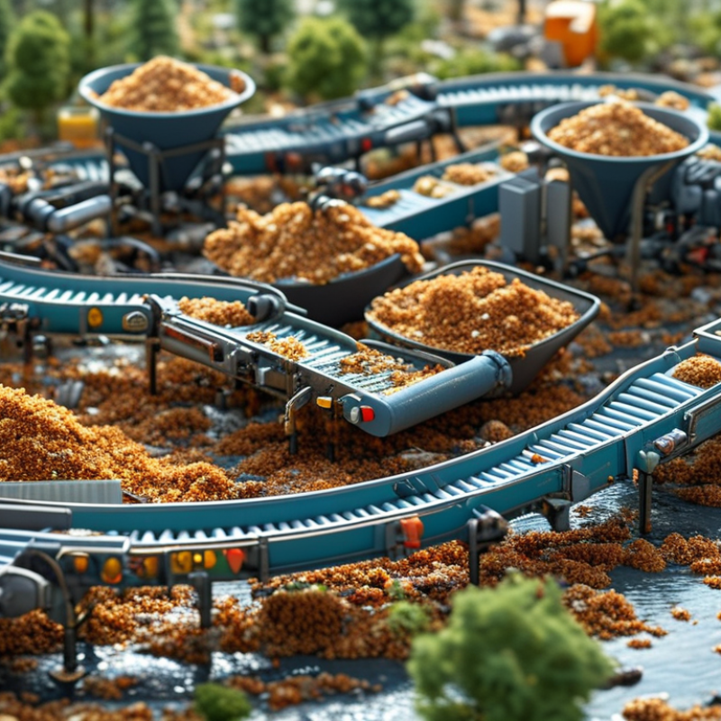
A waste feeding system is the equipment that moves waste from a storage area into a treatment process. It may serve an incinerator, anaerobic digester, composting line, or recovery facility. The system usually includes a receiving hopper, conveyors, a metering device, sensors, and protective barriers. Its main purpose is controlled delivery. Waste should enter at a steady rate, not in sudden piles that overload downstream equipment.
In daily operation, workers unload material into a hopper. A conveyor then carries it toward a shredder, furnace, or digestion chamber. A ram feeder may push bulky material through a sealed opening. Sensors check flow, weight, temperature, or blockages. Control software adjusts the feeding speed when conditions change. For example, wet waste often moves differently from dry waste. That difference matters.
The design is not perfect. Plastic film can wrap around shafts, while oversized objects may stop a conveyor. Operators inspect transfer points, clean buildup, and test emergency stops during scheduled maintenance. Good systems also limit dust, odors, and unauthorized access. Experience shows that regular inspection is often more valuable than complicated automation. The neat diagram is rarely the whole story. A feeding system needs practical adjustments, clear procedures, and reliable records to operate safely.
A waste feeding system receives, meters, and transfers waste into a treatment or processing line. The material profile below represents typical global municipal solid waste categories that may enter a feeding system by mass.
Feed systems commonly use a hopper, conveyor or screw feeder, metering controls, and safety sensors to maintain a steady material flow. Organic waste is the largest category, while paper, plastic, glass, metal, and other materials require controlled handling to reduce blockages and uneven feeding.
A waste feeding system moves prepared waste into a furnace, boiler, digester, or processing line at a controlled rate. Its main components must work together. The World Bank’s What a Waste 2.0 report estimates that global municipal waste could reach 3.4 billion tonnes annually by 2050. Reliable feeding will become more important.
The process usually begins with a receiving hopper. It stores waste and absorbs uneven deliveries. A grab crane or loader places material inside. A conveyor then carries waste toward a metering unit. Apron conveyors handle heavy loads well, while screw conveyors suit smaller, wetter materials. Shredders reduce oversized items. Screens and magnetic separators remove unsuitable material before feeding. Load cells, level sensors, and variable-speed drives regulate the flow. A control system watches blockages, temperature, and motor load. Small errors can still cause serious downtime. Design assumptions deserve regular review.
Tips: Keep the hopper walls clean and inspect conveyor skirts weekly. Measure moisture and particle size, not only weight. The UNEP Global Waste Management Outlook 2024 reports that municipal waste generation may rise from about 2.1 billion tonnes in 2023 to 3.8 billion tonnes by 2050. Therefore, operators should allow space for future capacity. A practical improvement is often simple: install inspection doors where workers can safely reach them. Fancy automation cannot fix poor access.
| System Dimension | Component or Feature | Main Function | Typical Materials or Design | Key Operating Considerations |
|---|---|---|---|---|
| Definition | Waste feeding system | Transfers prepared waste from storage or processing equipment to a treatment unit, such as a furnace, boiler, gasifier, or anaerobic digester. | Enclosed mechanical equipment with conveyors, hoppers, chutes, and control devices. | The system must provide a controlled, continuous, and safe feed despite variations in waste size, moisture, and composition. |
| Receiving and storage | Receiving hopper or bunker | Collects incoming waste and provides a buffer between delivery and the treatment process. | Reinforced steel, concrete bunker walls, abrasion-resistant liners, and sealed access areas. | Capacity is selected according to delivery frequency, treatment throughput, and required operating reserve. |
| Metering | Dosing hopper or metering bin | Regulates the amount of waste released into the conveying or feeding line. | Steel hopper with a variable-speed screw, belt, apron, or hydraulic extraction device. | Accurate metering helps maintain stable thermal output, residence time, and downstream process conditions. |
| Conveying | Belt, apron, screw, or chain conveyor | Moves waste from the storage area or preparation stage to the final feeder. | Carbon steel or stainless steel frames, heavy-duty chains, sealed bearings, and replaceable wear parts. | The conveyor type depends on waste density, particle size, moisture, inclination, and risk of wrapping or bridging. |
| Size reduction and preparation | Shredder, crusher, or pre-processing unit | Reduces oversized items and improves feed uniformity before the waste enters the treatment equipment. | Slow-speed or high-torque cutting equipment with replaceable knives, screens, or breaker bars. | Foreign objects, long flexible materials, and excessive moisture can affect throughput and increase blockage risk. |
| Final feeding | Ram feeder, rotary valve, screw feeder, or hydraulic pusher | Delivers waste into the reactor, furnace, boiler, or digester at a controlled rate. | Hydraulic cylinders, abrasion-resistant steel, rotary pockets, or enclosed screw flights. | The feeder must tolerate heat, abrasion, pressure differences, and potential backflow from the treatment chamber. |
| Air and odor control | Seals, extraction fan, and air-lock arrangement | Limits the escape of dust, odors, smoke, and process gases while maintaining controlled airflow. | Flexible seals, enclosed transfer points, induced-draft fans, and mechanical or rotary air locks. | Negative pressure is commonly used in waste handling areas to direct contaminated air toward treatment or filtration equipment. |
| Monitoring | Level, weight, speed, temperature, and blockage sensors | Measures operating conditions and detects empty, overloaded, overheated, or obstructed equipment. | Load cells, radar or ultrasonic level sensors, encoders, thermocouples, and vibration switches. | Sensor selection should reflect dust, moisture, corrosive gases, temperature, and the required measurement accuracy. |
| Control system | PLC, variable-frequency drives, and operator interface | Coordinates start-up, shutdown, speed control, alarms, interlocks, and automatic feed-rate adjustment. | Industrial control cabinet, programmable logic controller, motor drives, and human-machine interface. | Interlocks should prevent feeding when downstream equipment is stopped, blocked, overheated, or not ready. |
| Safety | Emergency stops, guards, access controls, and fire protection | Protects personnel from moving machinery, fire, hot surfaces, dust, and unexpected start-up. | Guarding, pull-cord switches, emergency-stop buttons, fire detection, water or inert-gas systems where appropriate. | Safety measures must be selected through a documented risk assessment and maintained throughout the equipment lifecycle. |
| Operating sequence | Receiving → preparation → metering → conveying → final feeding → treatment | Creates a continuous material path from waste intake to the treatment chamber. | The exact arrangement varies with waste type, treatment technology, site layout, and required capacity. | A reliable system balances throughput, feed consistency, energy use, maintenance access, containment, and process safety. |
A waste feeding system moves organic waste from delivery to a controlled treatment process. Its work begins with inspection, not pumping. The UNEP Food Waste Index Report 2024 estimates that households, food services, and retailers generated 1.05 billion tonnes of food waste in 2022. That volume makes dependable feeding equipment essential. At the receiving bay, operators weigh loads, check contaminants, and record moisture or temperature. Screens or manual tools remove large objects. The waste then enters a hopper. Simple, but important.
A conveyor or pump transfers the material to a shredder or pulper. Water may be added to create a consistent slurry. Magnets and grit separators protect downstream machinery. A buffer tank handles uneven deliveries. Sensors monitor level, temperature, and flow. A metering pump feeds the digester at a controlled rate. If the mixture becomes too thick, pipes may clog. If it becomes too wet, treatment efficiency can decline. During anaerobic digestion, microbes convert biodegradable solids into biogas and digestate. The IEA’s biogas sector analyses identify feedstock quality and stable operations as key limits to expansion. Real facilities are less tidy than diagrams suggest.
Tips: Keep a reject log. Calibrate weighing systems monthly. Wash transfer points daily. Inspect seals before leaks appear. Change feed rates gradually. Sudden loading can disturb microbial activity. Data helps, but operator judgment still matters.
Waste feeding systems are designed to move discarded materials into processing equipment safely and consistently. Their suitability depends on the waste’s moisture, size, density, and contamination level. In practice, operators often handle food scraps, vegetable residues, spoiled produce, and other biodegradable materials. These wastes are usually wet and soft, so pumps, conveyors, or hoppers can transport them efficiently.
Some systems can process packaging-free commercial food waste, agricultural residues, and organic material from kitchens or processing facilities. Shredders may reduce larger pieces first. Screens can remove stones, cutlery, or other unwanted objects. Grease-rich waste may require special handling because it can clog pipes and reduce feeding accuracy. Very dry materials behave differently and may need compactors or mechanical conveyors instead of liquid-based equipment.
The system should not receive every type of waste. Metals, glass, batteries, chemicals, medical waste, and pressurized containers can damage equipment or create serious hazards. Even small plastic fragments may reduce the quality of recycled organic output. Operators usually inspect incoming material and adjust feed speed when the waste changes. This sounds simple, but real waste streams are rarely consistent. A system may perform well one day and struggle the next. Moisture levels, unexpected contamination, and oversized pieces often explain the difference. Careful monitoring remains necessary.
A waste feeding system moves prepared waste into a processing unit at a controlled rate. It commonly includes a receiving hopper, conveyor, shredder, metering device, and discharge chute. Sensors monitor material levels and detect blockages. A ram or screw feeder may then push waste into a furnace or treatment chamber.
The main benefit is a steadier process. Even feeding can improve combustion, reduce sudden temperature changes, and support more consistent energy recovery. It also limits manual handling around dusty or hot areas. Proper feeding may reduce fuel waste and help operators maintain stable emissions performance. However, these benefits depend on suitable waste preparation. Wet, bulky, or mixed materials can bridge inside the hopper. They can also overload conveyors and cause uneven feeding.
Operating decisions require close attention. Operators should check moisture, particle size, density, and contamination before feeding. Daily inspections should cover bearings, seals, chains, sensors, and emergency stops. Build-up around the chute deserves quick action. Small deposits can become serious restrictions. Safety interlocks must be tested, not merely assumed to work. Maintenance records also help identify repeated failures and changing waste conditions. No system removes every problem. In practice, a design that works well in winter may struggle with wetter material during other seasons. Reviewing feed data and adjusting speed can improve reliability, although adjustments sometimes create new wear or throughput issues.
Copyright © 2025 The Toolroom Inc. All Rights Reserved.
Website Design St Louis by IQComputing