
A Digital Crimper is more than a powered tool with a screen. It is a controlled joining system for terminals, wires, and connectors. Unlike a basic hand crimper, it can monitor pressure, cycle count, tooling position, and production data. That information helps technicians identify weak crimps before they become costly failures.
Electrical connection specialist Gary Judd once said, “A crimp is only as good as the process that makes it.” This principle explains why Digital Crimper technology matters. The machine compresses a terminal around a conductor with carefully measured force. Sensors watch the cycle. Software compares the result with programmed limits. If the pressure, height, or position looks abnormal, the system can stop production or issue a warning.
The process sounds simple. It is not always simple. Wire size, insulation thickness, terminal material, die alignment, and operator setup can all change the final connection. A machine may display a perfect result, yet poor wire preparation can still weaken the joint. That detail deserves attention.
In practical use, a technician places the terminal and stripped wire into the tooling. The Digital Crimper then completes the compression consistently, often recording each cycle for quality review. Manufacturers use these records to support traceability and reduce inspection errors. Still, digital monitoring cannot replace proper calibration, sample testing, and trained judgment.
This article explains what a Digital Crimper is, how its working cycle functions, and which measurements matter. It also examines common setup mistakes. Real performance depends on disciplined use.
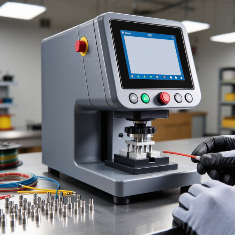
A digital crimper is an electric or battery-powered tool that joins a wire to a terminal with controlled pressure. Unlike a basic hand crimper, it uses sensors, a microcontroller, and a digital display. The system monitors force, stroke, or cycle completion. It then signals whether the connection meets the selected setting.
An operator places the stripped wire and terminal into matched dies. The motor closes them until the programmed force is reached. Some models record cycle counts, pressure values, and fault alerts. This matters as wire harness production grows. Grand View Research valued the global wire and cable market at about USD 216.6 billion in 2023. Its report projects continued growth through 2030, increasing pressure for consistent assembly. Digital crimpers can support that consistency, especially across repeated production runs.
However, a screen does not guarantee a reliable joint. A worn die, incorrect terminal, or poorly stripped conductor can still create failure. IPC/WHMA-A-620 provides widely used acceptance guidance for cable and harness workmanship. Technicians should combine digital readings with visual inspection, calibration checks, and periodic pull testing. The tool is only one part of the process. That point is easy to overlook.
In practice, digital crimping improves traceability, but it cannot replace trained judgment or suitable terminal selection. (Sources: Grand View Research, Wire and Cable Market Report, 2024; IPC/WHMA-A-620.)
A digital crimper is a precision tool for joining terminals to wires. It uses controlled pressure instead of guesswork. The digital display shows settings, force, cycle count, or battery status. This information helps technicians check each connection during repetitive work.
Inside, the controller manages the crimping cycle. A motor or hydraulic actuator moves the crimping jaws. Interchangeable dies shape the terminal around the conductor. A pressure sensor measures force and can detect incomplete compression. Some models stop automatically when the programmed force is reached. The power system may use a rechargeable battery or an external supply. A sturdy frame keeps the dies aligned. Even a small alignment error can damage a terminal or weaken the connection. In practice, readings are useful, but they are not perfect. Wire condition, terminal size, and operator technique still affect the result.
Tips: Match the die to the terminal and wire gauge. Clean the contact area before crimping. Set the correct force, then test a sample connection. Pull gently to check mechanical strength. Inspect the finished crimp for cracks, loose strands, or uneven compression. Keep the display visible while working. Recheck settings when changing materials. Age, dirt, and worn dies can produce misleading results. When a crimp looks acceptable but feels loose, stop and investigate rather than repeating the same cycle.
What Is a Digital Crimper and How Does It Work?
A digital crimper joins a terminal to a wire with controlled pressure. Its screen displays force, cycle count, and error codes. The operator first selects the correct die, terminal, wire size, and programmed force. This choice matters. IPC/WHMA-A-620 provides widely used acceptance guidance for crimped wire assemblies. A 2024 Grand View Research report valued the global wire and cable market at about USD 216.7 billion in 2023. More wiring means greater demand for repeatable connections.
The working cycle is direct. The operator strips the wire to a measured length. The terminal rests inside the die. The conductor strands must sit beneath the conductor barrel, not beyond it. After the foot pedal or control button starts the cycle, the motor drives the ram downward. The die compresses the barrel around the strands and insulation support. Sensors measure pressure and position during this movement. If readings fall outside limits, the machine can stop and flag the crimp. The operator then checks pull strength, conductor position, and barrel shape. Digital records can support quality audits, although records alone cannot prove every connection is safe. That part needs human judgment.
Tips: Keep the stripping blade sharp and verify wire length before production. Calibrate the force sensor on schedule. Inspect one finished crimp under bright light. A loose strand may look harmless. It is not. Record unusual results, even when the machine accepts the cycle. My practical caution is simple: a perfect display cannot correct a wrong terminal or damaged conductor.
A digital crimper uses an electrically powered actuator, a force-sensing system, and a controller to compress a terminal onto a wire. The operator selects the terminal and wire size, positions the parts, starts the cycle, and checks the digital result.
Note: The values shown are standard nominal copper conductor cross-sectional areas converted from common AWG sizes. They are reference values for selecting compatible tooling, not universal crimp-force settings.
A digital crimper is a powered hand tool that joins a wire with a terminal through controlled pressure. It uses a motor, sensor, and display to guide the crimping cycle. The tool measures force during compression. This helps technicians identify incomplete or excessive crimps before equipment is energized. A suitable die still matters. Digital control cannot correct the wrong terminal size.
Electrical assembly is one major application. Technicians use digital crimpers for control panels, battery cables, and industrial wiring. Consistent pressure helps reduce loose connections, exposed strands, and unnecessary heat. In solar installations, the tool supports repeatable connections in outdoor cable systems. Weather exposure makes small crimping errors more serious. Every connection deserves inspection.
Automotive repair teams also use these tools for harnesses, sensors, and power distribution cables. Telecommunications technicians apply them to communication wires where signal stability depends on clean contact. In production lines, stored crimp data can support quality checks and worker training. That record is useful, but not perfect. A careless wire strip can still weaken the joint. Operators should check conductor placement, terminal alignment, and pull strength. Calibration should be reviewed regularly, especially after heavy use. The display may look precise. Human judgment remains essential.
What Is a Digital Crimper and How Does It Work?
A digital crimper joins a wire and terminal with controlled pressure. The user places both parts inside a matching die. When the handles close, an internal sensor measures the applied force. A screen may show pressure, cycle status, or an error message. This feedback helps reduce loose crimps and excessive compression. The correct terminal, wire size, and die must still match. Digital guidance cannot repair a poor setup.
Safety Tips and Proper Maintenance
Keep fingers away from the closing dies. Wear safety glasses, especially when trimming wire or testing a finished connection. Check the tool before every use. Look for cracked handles, bent dies, loose fasteners, or damaged insulation. Never force a terminal into the wrong die. Stop immediately if the display shows an unusual reading or the tool feels unstable. Disconnect powered models before cleaning or clearing a jam.
Tips: Clean the jaws with a dry, lint-free cloth after use. Remove metal fragments from the die grooves. Store the crimper in a dry case, away from heat and moisture. Follow the manual for lubrication, battery care, and calibration intervals. A light pull test can reveal a weak connection, but it is not a complete quality check. I sometimes overlook small debris during busy work. That mistake matters. Even a clean-looking tool may need professional inspection when readings become inconsistent.
| Category | Item | Practical Information | Safety or Maintenance Note |
|---|---|---|---|
| Definition | Digital crimper | A powered crimping tool that uses an electronic control system and a display to monitor settings, operating status, battery condition, or completed cycles. | It is not automatically safer or more accurate than a manual tool; correct die selection and proper setup remain essential. |
| Main function | Terminal and connector crimping | The tool compresses a metal terminal around a stripped conductor to create a mechanically secure and electrically conductive connection. | A crimp should be formed only on the approved conductor and terminal combination; solder should not be used to compensate for a poor crimp. |
| Core components | Drive, jaws, dies, controller, display, and power source | The motor or hydraulic drive moves the jaws; interchangeable dies shape the terminal; the controller manages the cycle; the display provides status information. | Inspect jaws, pins, die cavities, trigger controls, housing, and cables before use. |
| How it works | Controlled compression cycle | After the terminal and wire are positioned, the tool advances the jaws through a programmed or trigger-controlled cycle and then releases or returns to its starting position. | Keep fingers, clothing, and loose objects away from the jaws during the entire cycle. |
| Digital controls | Display and electronic feedback | Depending on the tool, the display may show selected die information, battery level, cycle count, overload status, or a service warning. | Treat warning codes as instructions to stop and inspect the tool rather than repeatedly restarting it. |
| Typical applications | Electrical and wiring work | Common uses include insulated and non-insulated terminals, cable lugs, wire splices, and selected connector systems within the tool’s rated range. | Verify the tool’s approved wire-size range and connector type before starting a job. |
| Preparation | Select the correct die and terminal | Match the die cavity to the terminal design and conductor cross-sectional area or American Wire Gauge size specified by the tool or connector documentation. | Never force an oversized terminal into a smaller cavity or use a die that does not match the terminal profile. |
| Wire preparation | Strip and position the conductor | Remove insulation to the specified length without nicking or cutting the conductor. Insert the conductor fully into the terminal barrel before crimping. | Discard wires with damaged strands and keep insulation outside the electrical contact area unless the terminal design requires otherwise. |
| Operating sequence | Inspect, position, crimp, and release | Check the tool, install the die, place the terminal and wire, start the cycle, wait for full release, and remove the finished connection. | Do not interrupt a cycle by pulling on the wire. Use the designated manual-release mechanism if the jaws become stuck. |
| Quality check | Visual and mechanical inspection | A completed crimp should be centered, evenly formed, free from cracks, and firmly attached. A gentle pull test may be used when permitted by the applicable work standard. | Do not reuse a terminal that has been incorrectly crimped, crushed, or removed from a wire. |
| Electrical safety | De-energized work | Disconnect, isolate, and verify the absence of electrical power before crimping wires in an installation or assembly. | Use appropriate lockout and verification procedures where required. A crimper is not a substitute for electrical isolation. |
| Personal protection | Eye and hand protection | Safety glasses help protect against flying wire strands or metal fragments. Work gloves may be suitable when they do not reduce control of the tool. | Avoid loose gloves, jewelry, long hair, or clothing that could enter moving parts. |
| Battery safety | Rechargeable power source | Use the battery and charger specified for the tool. Keep contacts clean and charge the battery in a dry, ventilated location. | Stop using a battery that is swollen, leaking, unusually hot, cracked, or physically damaged. |
| Cleaning | Remove debris after use | Wipe the housing and jaws with a clean, dry or slightly damp cloth. Remove metal particles and insulation debris from die cavities. | Disconnect the battery or power source before cleaning. Do not spray liquid directly into the tool. |
| Lubrication | Moving parts and pivots | Lubricate only the points and with the lubricant specified in the tool’s service instructions. Some sealed mechanisms require no user lubrication. | Avoid oil on die surfaces, electrical contacts, sensors, and the display. |
| Inspection interval | Before every use and periodically | Check the tool before each job; perform a more detailed inspection after heavy use, a drop, exposure to moisture, or an abnormal crimp. | Remove the tool from service if cracks, excessive play, damaged insulation, inaccurate cycles, or hydraulic leakage is found. |
| Storage | Clean, dry, protected location | Store the tool with the jaws released, dies organized, and battery stored according to its charging and temperature requirements. | Protect the tool from excessive heat, moisture, dust, direct sunlight, and unauthorized use. |
| Professional service | Calibration and repair | Tools used for safety-critical or quality-controlled connections may require periodic force verification, calibration, or inspection by a qualified service provider. | Do not open the housing or modify the control system unless authorized service procedures specifically allow it. |
Copyright © 2025 The Toolroom Inc. All Rights Reserved.
Website Design St Louis by IQComputing